A couple of weeks ago Make: Online posted a link to a project on connecting a 7-Segment LED to the Arduino. It uses the technique of using one pin for each LED segment, which does get the job done, but it also gobbles a lot of pins in the process. I wanted to try to use binary data to reduce the number of pins used.
Method:
Binary data can code values 0 to 7 in 3 bits and values 0 to 15 in four, so a 7-segment LED could use as few as 3 lines for each display but taking advantage of that would require a logic circuit on the board to decode the data. I was short on transistors to make my own decoder, but I still have an assortment of 74LS logic devices I got from Jameco around 2003.
Unfortunately, all three of the three chips I had (74LS47, 74LS138, 74LS139) that would get me close to what I wanted assumed a common anode on my 7 segment display, and I had a common cathode display (RadioShack's stocked-in-store display). So I waited out the weekend and then went by Sparkfun and got a few of these common anode displays.
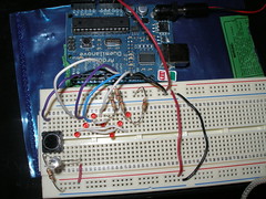
Back at home, I wired up two of the displays to two 74LS47 chips. The easy part of this was that matching up the diagrams of the two devices was a matter of drawing a line from little a to little a. The tougher part was putting a 100 ohm resistor in that line and routing it across my breadboard. I did get everything hooked up and running well on the 3 volts.
Next I had to get signal lines from the Arduino to the breadboard which quickly became a rat's nest of wires. I knew from my time in the shop that every wire was increasing the confusing and the potential for creating a fault I would never find, so I stopped and made a cable.
I had on hand a cat-5 cable my dog chewed up during one of her first couple of months with us. Slicing it open, I found 8 stranded wires twisted into four color-coded pairs. I used crimp connectors and two 1x4 housings to make an 8 to 8 cable to carry the data to each chip.
With the cable, it was time to write some code.
The 74LS47 takes 4 lines of binary coded data (BCD) and turns them into a map of the associated decimal number.
For my first pass, I used a switch case to set four separate variables for each display, each containing one of the four bits. This worked as long as I was sending the same data to each display. But the same thing could be accomplished with an extra set of jumpers on the breadboard, so clearly I needed different data to each.
This step ended up simplifying the code because using the switch case to set all 8 bits would require 99 cases. What I found trying to avoid that was bitRead(x,n). This allowed me to use the bits of my value as the code to send the chip.
The heart of my new sketch is this:
    for (d=0; d<4; d++){
     digitalWrite(Rled[d],bitRead(j,d));
     digitalWrite(Lled[d],bitRead(i,d));
   }
This loops through two arrays which contain the pins (i.e. 7,8,9,10) and sets the pin high or low depending on the value of that bit (d) in the current number (i or j).
Result:
The results are quite satisfactory. I'm using a 0 to 9 loop for the 10s digit and another 0 to 9 loop for the ones. The 10s increments once for each loop of the ones. The size of the full sketch is 2378 bytes and I'm using only 8 of 14 digital pins to get the output. This compares to 3212 bytes for my switch case code and 8 pins for the original example.
Next:
My next steps with this project are to use button input to affect the numbers displayed. My plan is to make a universal gaming die where the user selects 4, 6, 8, 10, 12, 20, or 100 faces, presses the go button, and gets a random output. Results to follow!
I ran across this project for a single 6-sided die at the Electronics Club website and I was intrigued by their use of a grouped logic for presenting the results. I wanted to use my Duemilanova for both the randomizer and the LED driver though. Here are my results.
The first step was to set up the breadboard circuit. I'm using a solderless breadboard so I ended up with the seven pips on a diagonal.
The logic of the circuit is this: every time an odd number is rolled on a die, the center pip is included. Every number other than one has pairs of pips showing, with or without the center.
So the center has a pin to itself (13), and the other pips are paired by the white jumpers. Each pair gets a pin, which allows me to represent 6 (actually 7) numbers using 4 pins -- and no decoder.
My first sketch computes a random number (using pin 0 as a seed as suggested in the randomize() documentation) from 1 to 6, turns on the appropriate pips, waits a second, then does it again.
Here's video:
And here's the sketch:
/* Die
computes a random number from 1 to 6 and displays it using 7 LEDs as a die face
The circuit: * LED connected from digital pin 13 to ground. * 2 LEDs in serial connected from digital pin 12 to ground. (2s place) * 2 LEDs in serial connected from digital pin 11 to ground. (4s place) * 2 LEDs in serial connected from digital pin 10 to ground. (6s place)
Created 26 Dec 2009 By Anne Speck
*/
int die1; // container for current value of die1 (possible future expansion) int basket; // variable for processing die values
int ledPin13 = 13; // LED connected to digital pin 13 int ledPin12 = 12; // 2 LEDs connected to digital pin 12 int ledPin11 = 11; // 2 LEDs connected to digital pin 11 int ledPin10 = 10; // 2 LEDs connected to digital pin 10
int one = LOW; int two = LOW; int four = LOW; int six =LOW;
// The setup() method runs once, when the sketch starts
void setup() { // initialize the digital pin as an output: pinMode(ledPin13, OUTPUT); pinMode(ledPin12, OUTPUT); pinMode(ledPin11, OUTPUT); pinMode(ledPin10, OUTPUT);
//use serial output for debugging Serial.begin(9600); }
// the loop() method runs over and over again, // as long as the Arduino has power
void loop() { // generate random number // if analog input pin 0 is unconnected, random analog // noise will cause the call to randomSeed() to generate // different seed numbers each time the sketch runs. // randomSeed() will then shuffle the random function. randomSeed(analogRead(0)); die1 = random(1, 7);
// translate number into pins for display basket = die1; if (basket%2) { //If there's a modulo, this is an odd number. basket--; one=HIGH; } if (basket == 6) { //If six, turn on sixes place and subtract two basket--; basket--; six=HIGH; } if (basket == 4) { //If four, turn on fours place and subtract two basket--; basket--; four=HIGH; } if (basket == 2) { //If this has a value it's two. basket=0; two=HIGH; }
digitalWrite(ledPin13, one); // set the LED on digitalWrite(ledPin12, two); // set the LED on digitalWrite(ledPin11, four); // set the LED on digitalWrite(ledPin10, six); // set the LED on
//serial output for debugging Serial.print("The number is: "); Serial.println(die1); Serial.print(one); Serial.print(two); Serial.print(four); Serial.println(six);
delay(1000); // wait for a second
//Reset all pins one = LOW; two = LOW; four = LOW; six =LOW;
I picked up my ArduinoDuemilanove board yesterday from Sparkfun and started working through Lady Ada's tutorial. This is from lesson 3. I wanted the lights to chase.
While it's been a couple of years since I've posted anything here, I've kept tinkering. And I'm hoping to do a whole lot more.
My current buzz is the Arduino culture. I love the open source nature of it. The community of people encouraging each other in Make:, in Instructables, and on Facebook.
It is also nice for me to see Arduino introductions in Craft: magazine, and women shown helping build projects in Make: magazine... which gives me hope that one of these days I will see women writing regularly in Make: or some othergeekyhardwaremagazine.
Still, progress is progress. Mythbusters may not have a lot of women experts to choose from but they do their best to make sure there are women doing interesting technical things on every show... and they're not just writing the documentation.
The freaky/cool think about the Arduino community is that in the early 80's my dad launched a product line from his company that went in exactly this direction. We called them hobby robots and tried to pitch them to teachers for classroom use. Which made me the youngest exhibitor at the First International Personal Robotics Convention. I cut my technical writing teeth writing code for and documenting our Elementary Automation kit, Mobile Mouse, a vision bot, and our 3 axis arm (all available for interfacing with the Commodore 64 and Apple IIe), but by 1990 the line had failed to take off and dad shut it down. I guess now I get to be the hobbyist.